
An average strand of human hair is 70-80 microns, or one-millionth of a meter, in diameter. The width of a particle that leads to the rejection of a batch of medication, a decrease in semiconductor wafer yield, or costly downtime in a liquid cooled data center may only be a fraction of that size.
Given the potential consequences, contamination control in high-purity systems is a key concern across industries ranging from semiconductor manufacturing, cryogenics, and pharmaceuticals to specialty gases and analytical instrumentation.
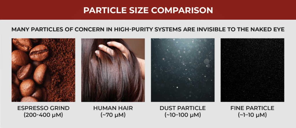
Maintaining system cleanliness requires more than cleanrooms, bunny suits, and filtering screens. Engineers must evaluate each element in a high-purity system to identify and manage potential sources of contamination. Understanding where particles originate is often the first step in designing systems that support long-term performance and reliability.
How Particles Are Generated in High-Purity Systems
In clean manufacturing environments where tight tolerances reign, contamination risks still abound. Particles may originate from operators and technicians in the form of skin cells, hair, sweat, and respiratory droplets. Airborne dust and debris in the surrounding environment—even static electricity—can introduce contaminants into the system. Process gases and fluids may contain chemical impurities that are compounded by the ingress of moisture or oxygen.
Equipment and tooling are another source of particle generation. Vibration, mechanical friction between moving parts, thermal cycling, pressure fluctuations, and fluid velocity may contribute to wear or dislodge existing contaminants over time. Outgassing from industrial plastics, sealants, and O-rings releases volatile organic compounds. Leaching is also a concern.
Many facilities have plans and processes to mitigate these risks. When it comes to equipment and tooling, contamination control begins long before a system is placed into service. During system design and component selection, engineers ask questions such as:
- Are materials compatible with the process gases and fluids?
- How will materials react to system cleaning agents?
- Are there risks where dissimilar materials meet?
- How is cleanliness defined and measured?
- What quality standards must components satisfy?
- How will suppliers verify those standards have been met?
- What handling and installation practices are required?
Scrutiny extends to every component in the fluid path, including valves, seals, tubing, and flexible connections. Hoses present a unique challenge in high-purity systems. As both a mechanical component and part of the process path, they must withstand demanding operating conditions while adhering to the same cleanliness standards as the surrounding system. This places increased emphasis on material selection, manufacturing methods, and handling practices when specifying flexible connections for high-purity applications.
Selecting Hose Materials for Contamination Control
In these sensitive systems, hoses for fluid and gas conveyance are made from various plastic and rubber compounds and several different metal alloys. When evaluating materials, engineers need to think about chemical compatibility, the impact of operating conditions and maintenance processes, and susceptibility to wear over time. In clean manufacturing environments, porosity, gas permeation, and outgassing also influence material selection.
Corrosion resistance charts published by hose manufacturers and Safety Data Sheets (SDS) provided by chemical manufacturers are valuable resources when evaluating compatibility. These references provide a useful starting point for material selection. With the exception of cryogenic applications–where only metal hose will do–there are many instances where stainless steel or a polymer-based alternative will be chemically compatible.
If an incompatible material is selected, the consequence is corrosion and eventual component failure. However, chemical compatibility is rarely black and white. Concentration, pressure, temperature, and environmental factors may change a material’s compatibility with a specific chemical.
As an example, iso-corrosion charts for phosphoric acid demonstrate why compatibility is rarely a simple yes-or-no decision. The compatibility of 316L stainless steel changes with both chemical concentration and operating temperature. Conditions that are acceptable in one application may not be suitable in another, reinforcing the need to evaluate compatibility within the context of the entire application.
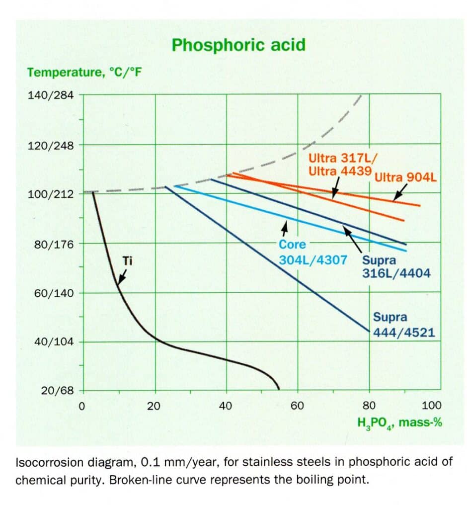
It is also important to recognize that compatibility data for liquid chemicals cannot be directly applied to high-purity gases, which require their own application-specific evaluation.
Additionally, maintenance procedures can introduce different chemicals into a system. Beyond assessing compatibility under normal operating conditions, engineers also need to consider all chemicals that will be running through the hose. Stainless steels 321 and 316L offer compatibility across a broader range of chemicals than polymer-based alternatives, a benefit when process media and maintenance chemicals differ.
Operating conditions also influence hose durability. Elevated temperatures accelerate the aging of many elastomeric materials, causing them to harden and crack. Beyond reducing hose performance, cracking may contribute to particulate contamination within the system. While metal hose is still subject to application-specific failure mechanisms, it is not susceptible to the same aging and embrittlement processes that affect elastomeric materials.
Beyond these concerns, plastic and rubber hoses are inherently porous, allowing the release of process gases and the intrusion of gases from the surrounding environment. While the former can result in the loss of valuable process media, the latter can introduce unwanted contaminants into sensitive systems.
Metal hoses, by contrast, are non-porous and highly resistant to heat and chemical attack. These characteristics support long service life and help make metal hose a compelling option in high-purity fluid and gas systems.
Material selection establishes the foundation for long-term system performance, but it is only part of the contamination-control equation. Manufacturing methods, cleaning processes, and handling practices can also influence the cleanliness of components before they are ever placed into service.
Ensuring Cleanliness Throughout the Manufacturing Process
During metal hose forming and assembly fabrication, moisture, residual debris, lubricants, and other contaminants may be introduced that must be removed before the hose is installed in a high-purity system.
Hose manufacturing methods vary significantly. Some rely on water or internal tooling, while others are designed to minimize or eliminate their use. For example, Clean ID hose is manufactured without internal tooling or lubricants to help minimize internal residue and reduce post-production cleaning requirements.
Once corrugated hose is formed and the braid is added, end fittings are welded on to create the completed metal hose assembly. High quality welds that minimize oxidation and avoid “sugaring” or burn through on the backside are essential to ensuring product cleanliness and maintaining corrosion resistance. TIG welding with argon purge gas is the proven process for delivering clean, leak-tight welds. Additional assurance comes from welds performed by experienced ASME Section IX-certified welders.
The completed assembly undergoes leak testing. While standard assembly testing includes an air under water test, hoses destined for high-purity applications are often subjected to more sensitive leak testing methods. For instance, helium mass spectrometry can detect leaks as small as 1 x 10-12 cubic centimeters per second.

End users may also specify cleanliness requirements beyond those provided by the hose manufacturer. While industries such as data centers do not have a single universal cleanliness specification, many organizations establish their own acceptance criteria. Examples include ASTM G93 Level C, IEST-STD-CC1246E, and CGA G-4.1. These requirements should be communicated during the quotation stage so appropriate cleaning procedures can be incorporated into the manufacturing process.
Manufacturing is only one step in ensuring system cleanliness. Proper handling, installation, and maintenance practices are equally important in preventing contaminants from entering the fluid path.
Contamination Control During Installation and Operation
Practices such as end capping, individual bagging, and controlled handling help preserve cleanliness once a hose assembly leaves the factory. Protective caps should remain in place until installation, and assemblies should be stored and handled in a manner that minimizes exposure to dirt, moisture, and other contaminants.
Installation and maintenance activities can also introduce contamination into a high-purity system. Improper handling may damage components in ways that create future contamination risks. For instance, extreme overbending can lead to fatigue cracking and subsequent introduction of metal particles into the system. General rules to avoid overbending include adhering to published minimum bend radii, avoiding pre-flexing prior to installation, and never bending a hose 90° at the fitting.
Routine inspections can identify corrosion, material degradation, physical damage, or other conditions before they affect cleanliness and ultimately impact system performance. If any of these items are observed, replacement should be considered.
- Loose, broken, bulged, frayed or worn braid
- Deformation of the hose, including braid wear, twisting, kinking, denting, flat spots
- Coupling slippage, cracks, severe dents or excess corrosion
- Traces of media on or around the assembly
- Loose or damaged guard or covers
- Indications of corrosion of the hose or braid
- Loose fitting attachments
- Hose assembly rubbing or making contact with adjacent machinery or piping
- Unreadable or missing identification or tag if this information is required
By considering contamination risks throughout the life of the assembly—from manufacturing through operation—engineers can better preserve the integrity of high-purity systems. While these considerations apply across many industries, semiconductor manufacturing places some of the most stringent cleanliness requirements on fluid and gas systems.
Semiconductor Manufacturing: A Particularly Demanding Environment
Few industries place greater demands on cleanliness and contamination control than semiconductor manufacturing. Flexible components used in chemical distribution systems, exhaust extraction, cooling lines, and vacuum applications are heavily scrutinized. Engineers are evaluating not only corrosion resistance and durability, but also surface condition.
Advanced manufacturing processes often utilize equipment with extremely small flow passages and tight tolerances, where microscopic contaminants can have an outsized impact. Tiny particles can compromise photoresist layers, leading to flawed patterns on the wafer. Dust can create pinholes, or voids, in coatings. Unwanted material in conductive layers can obstruct the current, causing overheating and device failure.
In semiconductor manufacturing, studies of ultra-pure water systems have demonstrated a measurable relationship between particle contamination and wafer defects, with reported yield impacts of 4–6%.2
Semiconductor fabrication relies on a variety of specialty gases and chemicals, many of which, like the etchant hydrogen fluoride (HF), are corrosive and require careful material selection to ensure compatibility. When an incompatible alloy is selected, corrosion mechanisms such as pitting and stress corrosion cracking can create surface imperfections where residue accumulates and contaminants become trapped, often long before leaks are detected.
Given these challenges, the semiconductor industry has developed standards through SEMI that specify the metallurgical cleanliness requirements, material composition, surface condition, and finish acceptance criteria of stainless steel components used in general purpose, high purity, and ultra-high purity semiconductor manufacturing applications. The objective is straightforward: eliminate potential contamination sources before they reach the process.
As semiconductor manufacturing processes become more complex and tolerances continue to tighten, there is less room for contamination-related failures. As a result, hose manufacturers are expected to deliver not only chemical compatibility and mechanical performance, but also the cleanliness, traceability, and quality assurance required by modern fabrication facilities. In these environments, maintaining cleanliness is not simply a quality objective. It is a critical aspect of system performance.
Supporting Cleanliness in High-Purity Systems
Particle management is an important consideration in many high-purity gas and fluid systems, where contaminants can affect equipment performance, product quality, and long-term reliability. While particles may originate from a variety of sources, system components—including flexible hoses—can play a role in supporting cleanliness objectives through thoughtful design, material selection, manufacturing methods, and handling practices.
Maintaining cleanliness requires attention at every stage of a component’s life cycle from material selection and manufacturing through installation, operation, and maintenance. By identifying and managing potential sources of contamination throughout the fluid path, organizations can support reliable operation in even the most demanding high-purity applications.

Footnotes
[1] British Stainless Steel Association (BSSA). Selection of Stainless Steels for Handling Phosphoric Acid (H₃PO₄). https://bssa.org.uk/bssa_articles/selection-of-stainless-steels-for-handling-phosphoric-acid-h3po4/
[2] F. Wali, D. Martin Knotter, A. Mud, and F. G. Kuper, “Impact of Particles in Ultra Pure Water on Random Yield Loss in IC Production,” Microelectronic Engineering, vol. 86, no. 2, pp. 140–144, Feb. 2009.