Forming and Welding the Tube
At Penflex, metal hose is manufactured from stainless steel strip. Continuous coils are formed into tube and the longitudinal seam is welded. The weld is a full-penetration butt weld. The weld is TIG welded. “TIG” stands for “Tungsten Inert Gas”. The tungsten is the electrode which means it is the conductor being used to carry the current (which supplies the heat for welding). The tungsten is not consumed during the welding process, so no material from the tungsten is transferred to the tube. All of the material which melts into the weld joint comes from the strip itself. No filler material is added to the longitudinal weld. The inert gas used in the welding process is argon. Inert means “non-reactive”. When the high heat from the weld current causes the two edges of the joint to melt in the presence of oxygen, this oxygen reacts with the elements in the metal to form oxides. The effect of this oxidation is an area which may be more susceptible to corrosion than the adjacent base metal. For this reason, argon is introduced into the area right where the electrode is. This is called “purging” the weld. The argon flow pushes all of the oxygen out of the way so that it can’t react with the metal. Since the argon is an “inert gas”, it does not have any effect. At Penflex, the inside of the tube is “completely purged” as argon is introduced and accumulated in the enclosed volume of the tube. Likewise, argon is flowing in the area of the tungsten on the outside of the tube, but because this area is open to the atmosphere, the argon flow must be constant; it doesn’t accumulate.
The Transformation from Tube to Hose: Mechanical Corrugation Method
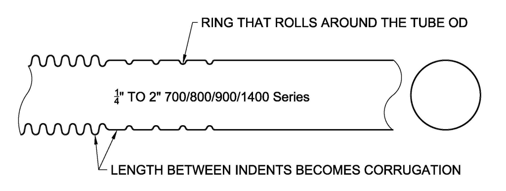
The base metal thickness used in corrugated hose sizes from 1/4″ to 2″ varies from .008″ to .024″ depending on the need to resist pressure or corrosion. The ratio of the metal thickness to the diameter of the tube is relatively large, so the tube is somewhat stiff in terms of deflection and strong in terms of resistance against crushing. For this reason, the hose sizes from 1/4″ to 2″ can be formed by “scoring from the outside”: When the tube is fed into the corrugator, it goes through a “cut ring” which rolls around it, pushing into the tube. The result is a “score” or a slight “neck-down” of the tube at uniform intervals as each section advances. These “neck-down” areas will ultimately become the “valleys” of the corrugations. The tooling is designed to have a smooth radius to minimize stress concentrations. Next, a pair of “C-shaped” tools on the corrugating machine called “jaws” clamp onto the tube right on the “scored” section. Then a second set of jaws clamps onto the adjacent “necked-down” section. One of these sets of jaws is stationary and the other set moves towards the stationary one. This causes the tube material between the jaws to “buckle up” into a curved shape to form the corrugations. The spacing between the “cuts” determines the length of material available to form the corrugation: The longer the space between “cuts”, the “taller” the corrugation. The height of the corrugation relative to the ID of the hose is sometimes referred to as the “profile” of the hose. That is, we say that one hose has a “higher profile” than another if the difference between its OD and ID is greater than the same difference on the other hose.
The Transformation from Tube to Hose: Hydraulically-formed Method
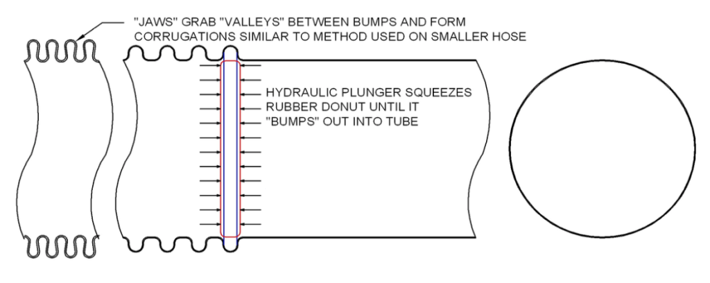
As the tube size gets larger and larger, the thickness of the tube “wall” gets very thin in proportion to the diameter. The tube is not very “stiff” compared to the smaller sizes. In fact, the tube could be manually squeezed with little force and made into an oval shape. If you tried to use the “cut ring” process on this tube to form hose, the walls of the tube would “buckle-in” or collapse at the cut stage. For this reason, the larger size hoses are formed instead by pushing the metal “outward” from the tube rather than inward. This can be accomplished in several ways. At Penflex, the tube is slipped over a “bumping rubber” shaped something like a donut which fits just inside the tube. A hydraulic plunger squeezes the donut. As it flattens out, it also widens outward on its diameter and pushes into the wall of the tube, drawing the material from the tube up into a “bulge”.
When the pressure on the plunger is removed, the elastic nature of the “bumping rubber” allows it to go back to its original shape. The tube advances a certain distance and then the process is repeated. At Penflex, each individual corrugation is formed one at a time. We refer to this method as “Hydraulically-formed” because a hydraulic plunger is used to create the force to push the material outward to form the corrugations. “Hydraulically formed” is not to be confused with another method of metal forming called “hydro-forming”. In hydro-forming, the force used to push the metal outward to form the corrugation is generated by water instead of a compressed rubber donut. The water pressure from inside the tube pushes the metal into a “die” on the outside of the tube which gives the “bump” its shape. Hydro-forming may be used to form the corrugations individually, or in a group of several “humps” all at once in a “multi-station” form. Usually, the hydro-forming method is used on thinner walled tube and the thicker wall hoses are formed using the “bumping rubber” hydraulic method. At Penflex, all hoses sizes 2-1/2″ and above are made using the “bumping rubber” hydraulic method. After the bumps are put in the tube, the stationary and moveable jaws grab the tube in the “valleys” between the corrugations. The moveable jaws press towards the stationary ones to form the corrugations. This step in the process is similar to that used in the mechanical corrugation method.
Thin-wall Hose Combines Tube Forming and Corrugation: Process #3 – Continuously-formed Method (P3)
The third method of forming hose is similar to the P1 process because it also mechanically forms from the outside. Unlike the P1 and P2 processes, which begin with a distinct length of formed tube, loaded and moved in an analog fashion through one stage of forming at a time, the P3 method starts with flat strip which continuously moves through the tube-forming and welding stations and then directly into the corrugation forming stations. Here, rollers move around the outside of the tube while the tube moves at a constant speed through the forming stations. The thickness of the strip used is much thinner than in the P1 process, so the “work” being done from the outside to shape the corrugations must be done in multiple small steps to avoid damage to the tube. For the same reason, the outside of the tube also must be more heavily lubricated than with the P1 process (to avoid stress on the thin-walled tube), so there is an in-line “rinse-off” station. The fact that the strip is being continuously fed into the line allows longer lengths to be manufactured. In the P1 process, the length of the hose is limited by the length of straight tube that can be manufactured in the first step of the process. In the P3 process, it is limited only be the size of the collector “pot” into which the finished hose is coiled and the practical issues of handling, testing and inspecting that coil.