Molten Sulfur Hoses
Recommended Specification for Molten Sulfur Hoses
Revision 1: October 2022
1.0 Scope
This document lays out considerations for the design, fabrication, installation, and maintenance of hoses used in molten sulfur service. These components are steam jacketed to maintain elevated temperatures. This ensures molten state is maintained.
2.0 Hose Design
2.1 Alloy Selection
For the inner hose, the 300 Series austenitic stainless steels—304, 316L, and 321 (UNS S30400, S31603, and S32100)—are suitable options. NACE’s Corrosion Data Survey shows Type 304 has a corrosion rate in molten sulfur at 325°F of 20-50 mils per year (mpy), while Type 316L has a rate of <20 mpy and the Inconel® alloys—such as Inconel® 600 and Inconel® 625—have corrosion rates of less than <2 mpy.
As Types 304 and 316L have predicted rates of corrosion in excess of the NAHAD recommended 2 mpy, Inconel® 625 (UNS N06625) may be a more suitable option depending on operating conditions. In the case of the former, recommended braid is Type 304 (UNS S30400). In the case of the latter, recommended braid is Inconel® 625 (UNS N06625).
For the outer hose, the 300 Series austenitic stainless steels—304, 316L, and 321 (UNS S30400, S31603, and S32100)—are suitable options, unless inner core is Inconel® 625, in which case recommended outer hose is Inconel® 625. In the case of the former, as steam systems can contain chlorides, and 316L is better suited to resist chloride corrosion, 316L may be preferred for the outer hose.
When hoses are made using one of the 300 Series stainless steels, wetted end fittings shall be specified by the owner. When hoses are made using Inconel® 625, wetted end fittings shall be constructed of the same material as the inner core.
2.2 Working Pressure
End users should determine working pressure. In the case of rail car loading and unloading, it is recommended that minimum pressure ratings equal the pressure setting of the relief device to which the hose is attached.
With two hoses and two kinds of flow media, there’s potential for a pressure differential. The consequence of building an assembly with such a difference in pressures could result in buckling of the inner hose. This could then lead to failure. Additional testing and analysis are needed. We recommend designers avoid a scenario where the pressure of the outer hose exceeds that of the inner hose.
For more information about steam jacketed hoses, please see this engineering bulletin.
2.3 Design Pressure
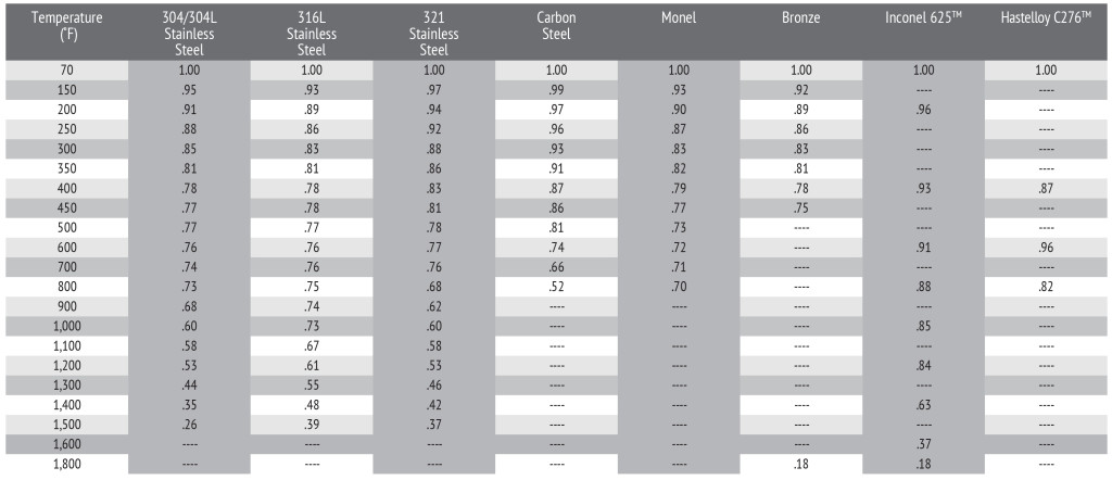
Hoses are capable of operating at the MAWP up to 70°F, above which derating factors must be considered. The braid alloy shall be considered the limiting factor when determining the pressure rating at temperatures over 70°F.
3.0 Hose Construction
3.1 Strip
Recommended hose shall be manufactured from following strip.
Inconel® 625 (UNS N06625) strip per ASTM B443-00e1 standard Grade 1 (AMS 5599F) with the following physical properties:
- Elongation: 30% minimum in 2 inches
- Temper: Fully annealed
- Minimum Yield Strength: 60,000 psi
- Minimum Tensile Strength: 120,000 psi
316LSS/321SS (UNS S31603/UNS S32100) strip per ASTM A240 with the following physical properties:
- Elongation: 45% minimum in 2 inches
- Temper: Fully Annealed B83 Max Rockwell (160.5 max on HV scale)
- Maximum Yield: 49,000 psi
- Tensile Strength: 75,000 – 100,000 psi
All hose shall be supplied with original mill test reports indicating the strip thickness and heat lot of the final assembly.
3.2 Strip Thickness
As corrosion wears material away, a thinner wall construction will compromise hose integrity sooner than a heavier wall construction. Metal hose shall conform to the minimum wall thickness as specified in Table 1 for 300 series stainless steels and Inconel® 625.
3.3 Manufacture
All hose shall have annular corrugations produced using mechanical methods.
4.0 Braid Construction
Braid for sizes up to and including 4” nominal size shall be beamed braid while braid for nominal sizes 6” and larger shall be braided braid. Braid splicing is not permitted. Braid constructions shall be calculated with a 4 to 1 safety factor to determine the working pressure. Recommended braid constructions are specified in Table 1 for 300 stainless steels and Inconel® 625.
4.1 Braid Alloy
As specified by the Owner, braid shall be manufactured from Inconel® 625 (UNS N06625), 304, 304L or 316L wire (UNS S30400 or S30403, respectively).
All Inconel® 625 (UNS N06625) wire per ASTM B443-00e1 standard Grade 1 or ASTM B166-04 shall have the following physical properties:
- Ultimate Elongation: 23% minimum in 10 inches
- Yield Strength: 30,000 PSI minimum
- Tensile Strength: 80,000 – 155,000 psi
All stainless steel wire per ASTM A580 shall have the following physical properties:
- Ultimate Elongation: 35% min / 50% max
- Yield Strength: 40,000 – 60,000 psi
- Tensile Strength: 105,000 – 125,000 psi
All braid shall be supplied with original mill test reports indicating the wire diameter.
4.2 Assembly Welding
The corrugated tube and braids shall be joined with a cap weld using TIG welding process, under an argon purge. The cap weld shall be completed before the attachment by welding of any end fittings. All welds shall be performed in accordance with ASME Section IX.
The braid sleeve shall cover a minimum of three convolutions.
End fittings shall be specified by the owner at time of purchase.
4.3 Tagging
The assembly shall have a permanent stainless steel tag attached to the hose with the following information:
- Hose ID and Length, or Part Number
- Manufacturer
- Date of Manufacture
- Maximum Working Pressure
5.0 Assembly Testing
5.1 Test Pressure
Prior to service, it is recommended each hose be tested at room temperature. Any indication of leaks is cause for rejection.
Each hose should undergo a high-pressure structural test at one-and-a-half (1.5) times the MAWP for at least ten (10) minutes. If the high-pressure test is administered with water, the hose must be subjected to a drying procedure to assure that adequate moisture is removed from the interior of the hose.
6.0 Cleaning
Prior to shipping, each hose assembly shall be cleaned to remove hydrocarbons, foreign materials and standing water.
7.0 Shipping
Hose assemblies shall be wrapped in water-tight packaging and boxed in containers that will prevent damage to the hose in transit. Hoses shall be shipped with securely fitted pipe caps or covers on the end fittings to prevent debris from entering the hose.
8.0 Installation & Use
8.1 Avoid Torque
Do not twist the hose assembly during installation when aligning the bolt holes in a flange or in making up pipe threads. The utilization of lap joint flanges or pipe unions will minimize this condition. It is recommended that two wrenches be used in making the union connection: one to prevent the hose from twisting and the other to tighten the coupling.
8.2 Out-of-Plane Flexing
To prevent out-of-plane flexing in an installation, always install the hose so that the flexing takes place in only one plane. This plane must be the plane in which the bending occurs.
8.3 Over-Bending
The repetitive bending of a hose to a radius smaller than the radius listed in the specification tables for corrugated hose will result in premature hose failure. Always provide sufficient length to prevent over bending and to eliminate strain on the hose and install flexible connectors so that the bend is as close to the center of the connector as possible.
8.4 Avoid Sharp Bends
Utilize sound geometric configurations that avoid sharp bends, especially near the end fittings of the assembly.
8.5 Provide Support
When installing the assembly in a horizontal loop, provide support for the arms to prevent the hose from sagging.
8.6 Axial Compression
A piping system which utilizes metal hose to absorb movement must be properly anchored and/or guided. Always support the piping to prevent excessive weight from compressing the hose and relaxing the braid tension.
8.7 Handle Carefully
Avoid careless handling of the hose assembly. Don’t “pre-flex” a hose to limber it up as overbending could cause damage and result in leakage. Don’t apply a wrench to a hose, collar, or assembly. Only wrench on the fitting hex flats and don’t try to stretch or compress a hose to fit an installation. This could affect the pressure carry capability of the hose. Always lift or carry metal hose to prevent abrasion damage particularly to braided corrugated hose. Store metal hose assemblies away from areas where it can be subjected to spillage, corrosive fumes or sprays, weld splatter, etc.
9.0 Hose Inspection
Periodically inspect hose assemblies to recognize features which lead to failure and proactively schedule replacement before actual failures occur. If any of these items are observed, replacements should be considered.
- Loose, broken, bulged, frayed, or worn braid
- Deformation of the hose, including braid wear, twisting, kinking, denting, flat spots
- Coupling slippage, cracks, severe dents, or excess corrosion
- Traces of media on or around the assembly
- Loose or damaged guard or covers
- Indications of corrosion of the hose or braid
- Loose fitting attachments
- Hose assembly rubbing or making contact with adjacent machinery or piping
- Unreadable or missing identification or tag if this information is required
Table 1: Assembly Construction Single Braid
| Hose ID | Min Wall Thickness |
Min Convo- lutions/Ft |
Min Wire Diameter |
Min # Braid Wires |
Min Burst Pressure @ 70°F |
|
| 300 Series | ½” | 0.010” | 86 | 0.014” | 216 | 4960 |
| ¾” | 0.015” | 60 | 0.014” | 324 | 3760 | |
| 1” | 0.015” | 50 | 0.014” | 360 | 2520 | |
| 11/2” | 0.015” | 42 | 0.016” | 480 | 2000 | |
| 2” | 0.015” | 40 | 0.020” | 480 | 2128 | |
| 3” | 0.015” | 27 | 0.020” | 648 | 1600 | |
| 4” | 0.015” | 26 | 0.020” | 792 | 1200 | |
| 6” | 0.018” | 24 | 0.020” | 1152 | 660 | |
| 8” | 0.020” | 18 | 0.024” | 2016 | 934 | |
| Inconel® 625 | ½” | 0.010” | 42 | 0.014” | 216 | 4301 |
| ¾” | 0.015” | 30 | 0.014” | 324 | 3168 | |
| 1” | 0.015” | 25 | 0.014” | 360 | 2285 | |
| 11/2” | 0.015” | 21 | 0.016” | 480 | 1887 | |
| 2” | 0.015” | 20 | 0.020” | 480 | 2064 | |
| 3” | 0.015” | 27 | 0.020” | 648 | 1264 | |
| 4” | 0.020” | 26 | 0.020” | 792 | 927 | |
| 6” | 0.020” | 24 | 0.020” | 1152 | 660 | |
| 8” | 0.020” | 18 | 0.024″ | 2016 | 934 |
Note: To print, please click here.