Engineering Bulletin #173
How Many Welds are There?
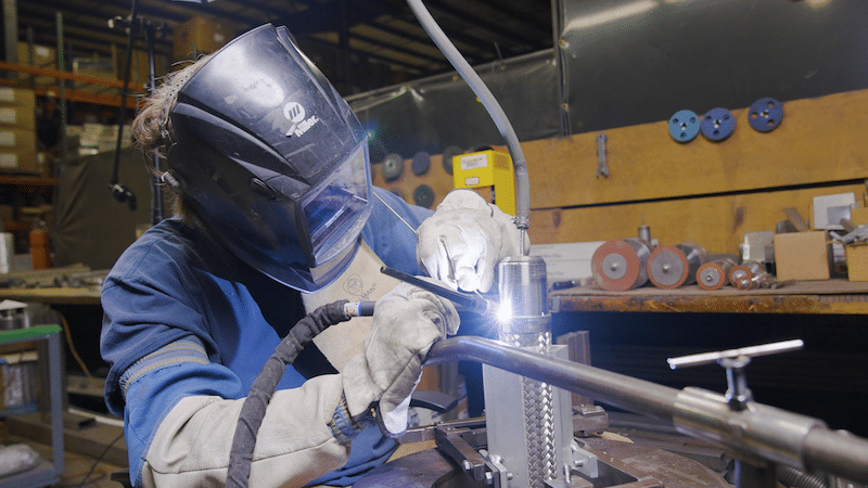
The typical metal hose assembly has four welds: two cap passes and two fitting attachment welds. (There are actually FIVE welds in a typical assembly if we include the longitudinal weld seam. This bulletin will, however, focus only on manual welds.)
Techniques for executing a successful cap pass were discussed in a previous bulletin; here we’ll take a look at the most common types of fitting attachment welds, what it takes to perform them, and common design considerations.
Direct Fitting Attachment
The most common fitting attachment method is the direct fitting attachment method, or the direct connect method.
The direct fitting attachment method is a two-step process which begins with a cap pass. The hose is cut in the valley, what we would call a standard cut. Braid is then pulled 1/16” of an inch above the edge of the hose and the ferrule is aligned with the edge of the hose before the welder completes a cap pass to join these components.
Once hose, braid and ferrule are joined via cap pass, the welder places the end fitting atop the cap pass. The end fitting must be level on the hose and centered before being tacked into place.
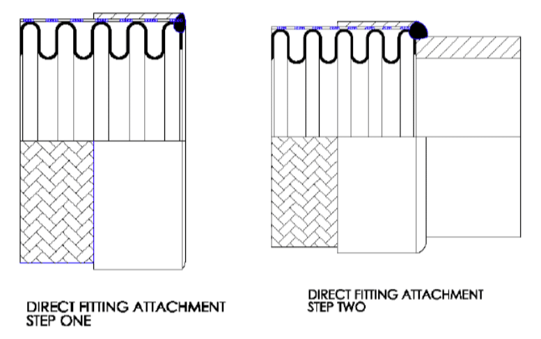
The welder then uses the proper filler rod and amperage and welds the fitting to the hose using an argon purge. There must be fusion between the first and second welds, though you do not want to burn through the fitting wall or remelt the cap pass.
Good fitting attachment welds will show a nice even weave pattern with coloring that indicates proper gas coverage. Welds should be shiny, rather than dull and gray. Assuming properly executed welds, the direct fitting attachment method has been verified by burst testing to achieve the full catalog pressure rating.

Brightly colored with an even wave indicate well-executed fitting attachment welds.
Discoloration in excess of acceptable limits would indicate purging was not done correctly and too much oxygen got into the weld. A “V” wave pattern would indicate too much heat, while a “V” wave pattern with a horizontal line through the middle would indicate both too fast of a travel speed and excessive amps.

Discoloration (left) and a “V” pattern in weld bead (right) are examples of poorly
executed fitting attachment welds.

Smooth Transition Fitting Attachment
Increasingly, in applications with extremely low tolerance for contamination, the smooth transition fitting attachment method is used. Here, the fitting is reverse beveled on the inside, the hose is often cut at the crest, and a slight gap is left between hose and fitting to allow for complete fusion of components with disparate thicknesses.
This additional preparation ensures a crevice and burr free connection. Crevices, as can be found behind the lip of a standard cut hose or which can result from lack of complete fusion, offer space for residue build-up that could eventually contaminate flow media. Altering the weld geometry with the crest cut and beveled end fitting safeguards the assembly from any debris from the hose cutting process or from operation that could get trapped inside the hose.
Reducing potential for contamination makes smooth transition attachment appealing to users in specific marketing, especially those in the cryogenic and pharmaceutical spaces. Chlorine Transfer Hoses, if they are to be in compliance with The Chlorine Institute’s Pamphlet 6, also must have smooth transition welds.
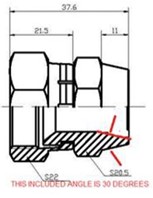
Here’s a look at how we would prepare a JIC fitting for a smooth transition attachment. Note, if the outside wall of the fitting is already tapered (for example 10° on the weld end of the female JIC) the taper on the inside need only be 10° – 20° to achieve the desired net angle of 20° – 30°.
Common End Fittings for Hose Assemblies
Beyond the pipe threads shown in the picture of nice welds above, other common end fittings include hex male NPTs, female JICs, and various kinds of fixed or floating flanges, the latter paired with stub ends.
Important Design Consideration
The outside circumference of the end fitting must overlap with the edge of the cap pass if the weld is to reach its full pressure bearing capabilities. As tube sizes are measured by outer diameter (OD) and hose sizes are measured by inner diameter (ID), the potential for a mismatch is greatest when attaching tube ends. As an example, there is little overlap between a 1” hose and a 1” tube end.
Some adjustment is needed, especially if the hose will be used in a high-pressure application. Solutions include opting for a smaller hose so there is more overlap–for instance a ¾” hose with 1” tube ends–or, if the same dimensions are needed, flaring the end of the tube to match the hose in order to create that needed overlap. This latter option would, however, also compromise pressure capacity and is not a sound practice for high pressure applications. Lastly, there are special tube size reducers, but they are expensive and also have lower pressure capacity.
Dissimilar Materials: When is it Okay?
Typically if a hose is 316L, we’ll use 316L end fittings. Using similar materials ensures the characteristics of the parent materials remain intact, and while most welders are qualified to welding procedures for joining similar materials, welding dissimilar materials requires separate weld procedures.
There is a common exception to the rule however! When working with floating flanges or raised face slip-on flanges, you’ll also need a stub end. Since the flange does not come into contact with flow media, only the stub end, the flange can be a different material and there is no issue.
Accessories
While four is the number of welds on a typical hose assembly, there are accessories added to hoses that increase this number. Accessories like an inside interlocked liner–used in high-flow applications–or an outside interlocked armor–used as an abrasion guard or bend restrictor–increase the number of welds on an assembly.
Penflex Welder Training
High caliber end fitting attachment welds are consistently achievable with proper training. Penflex offers a one-week ASME Section IX-certified program for welders with mid-level experience. The training is designed to improve technique, and perfecting fitting attachment welds is one of the skills achieved through the training.
Online Welder Training Course
For welders planning to attend Penflex’s Welder Program, or for those who have already completed it and are looking for a refresher, we offer an online welder training course. In the span of 30 minutes, our Certified Welding Educator reviews materials, join configurations, assembly prep and technique for cap and end fitting attachment welds.