What’s possible. What’s not. And an in-depth discussion on setting–and managing–realistic expectations.
Author Archive
Why Tolerances Can’t Be Zero
Note: To print this bulletin on metal hose tolerances, please click here.
There’s a certain satisfaction when things line up just right. When something runs like clockwork, or fits like a glove. Without discrete units of measurement, it’s easy to assume a perfect fit.
Dive into manufacturing and it’s a world of numbers. Tape measures, calipers, micrometers. In the metal hose industry, working with sheet metal, strip material is measured in thousandths of an inch. Assembly drawings mark overall length to a similar degree. No longer just a “feel,” fit now has defined measurements.
Once we know precisely what something is, we also know precisely what it is not. Stainless steel strip that is .018” thick is incredibly thin, but not as thin as strip that is .010” thick. To many the difference may not be noticeable. To others–and to our machines–it’s all too apparent.
But just how strictly must requested dimensions be matched?
Tolerance: Range of Acceptability
While our thickest strip (.035”) will not run in machines designed to make hose using our thinnest strip (.006”), and vice versa, each machine does have a (smaller) range of acceptable thicknesses. We refer to these ranges as tolerances.
For our thinnest strip, tolerance is +/- .00030” meaning the machine can run strip so long as it falls within this defined range on either side of .006”. From measuring the thickness of strip to the length of an assembly, measurements are taken throughout the manufacturing process to ensure dimensions fall within predetermined tolerances.
Why Tolerances are Important in Fluid Conveyance
Since metal hose assemblies are connected into an existing piping system or attached to a piece of equipment, parameters are needed to ensure the component fits with what is already there.
Industry association NAHAD has published guidelines on assembly overall length tolerances. This is considered the standard.
 *Source: Corrugated Metal Hose Assembly Specification Guidelines, by NAHAD.
In the drawing below, this 1½” assembly has an overall length (OAL) of 24”. In line with the NAHAD guidelines, the tolerance is +/- ⅝.” The hose will fit into its chosen application so long as its OAL ranges from 23⅜” – 24⅝”.

Setting Realistic Expectations
Since the allowances of our manufacturing processes are so small, we understand the need for close tolerances. However, it is important to set realistic expectations for metal hose.
The unique flexing characteristics of metal hose limit how tight tolerance can be. For one, when the hose is prepped for an assembly, it is cut in the valley of a corrugation. Compared to a straight tube where a 1-foot piece will match another 1-foot piece, a 1-foot section of corrugated hose may not exactly match another 1-foot section because of this requirement for a valley cut.
An exact 1-foot measurement may stop and start along the sidewalls, crests or valleys of corrugations at each end. There’s no guarantee that the corrugation valleys will align exactly with the designed measurement. This can sometimes be corrected by adjusting the length of the fitting, but some fittings, such as flanges, are not modifiable.
For another, a hose’s ability to flex means it likely will not return to the exact same length once bent. Storing, testing and shipping can all change the length of a hose after it is made. This can be a point of frustration to the perfectionist, but it’s important to note too that hoses typically elongate once pressurized.
The geometric properties that allow metal hoses to absorb movement also mean an assembly’s length does not remain exactly the same throughout its life. It is now easier to see why tolerances cannot be zero.
Designing to Account for Tolerances
As metal hose typically has larger tolerances compared to machined parts, it is not always suited for critically tight applications. When designing a system for the first time, it is ideal to have some redundant length so that the assembly is not always on the limit of recommended use. This is applicable to loops, where the added length will create a larger bend radius and help increase the cycle life of the assembly. For straight lengths, hoses should be kept on the shorter side to limit the effect of loose braid in fabrication or be built in such a way that there is some axial give to allow the hose to elongate.
When replacing hoses in low tolerance, straight configurations, hoses should be built slightly shorter. A shorter hose can be tightened into place, whereas if a longer hose is compressed to fit a tight space, failure is likely. Of course, this type of configuration should be avoided if possible and alternatives such as expansion joints should be considered.
Systems that use metal hose must be designed to account for the inherent tolerance associated with metal hose assemblies. Tools on our website can help find the minimum length for certain applications. However, engineers are always standing by to assist.
Note: To print this bulletin on metal hose tolerances, please click here.
Build Your Welding Skills
Penflex’s new online welder training is now available!
Fitting Attachment Welds for Metal Hose Assemblies
Note: To print this bulletin on fitting attachment welds for metal hose assemblies, please click here.
How Many Welds are There?
The typical metal hose assembly has four welds: two cap passes and two fitting attachment welds. (There are actually FIVE welds in a typical assembly if we include the longitudinal weld seam. This bulletin will, however, focus only on manual welds.)
Techniques for executing a successful cap pass were discussed in a previous bulletin; here we’ll take a look at the most common types of fitting attachment welds, what it takes to perform them, and common design considerations.
Direct Fitting Attachment
The most common fitting attachment method is the direct fitting attachment method, or the direct connect method.
The direct fitting attachment method is a two-step process which begins with a cap pass. The hose is cut in the valley, what we would call a standard cut. Braid is then pulled 1/16” of an inch above the edge of the hose and the ferrule is aligned with the edge of the hose before the welder completes a cap pass to join these components.
Once hose, braid and ferrule are joined via cap pass, the welder places the end fitting atop the cap pass. The end fitting must be level on the hose and centered before being tacked into place.
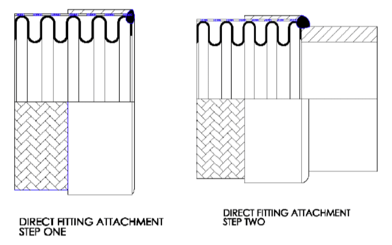
The welder then uses the proper filler rod and amperage and welds the fitting to the hose using an argon purge. There must be fusion between the first and second welds, though you do not want to burn through the fitting wall or remelt the cap pass.
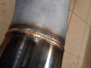
A good fitting attachment weld will show a nice even weave pattern with coloring that indicates proper gas coverage. Welds should be shiny, rather than dull and gray.

Brightly colored with an even wave indicate a well-executed fitting attachment weld.
Discoloration in excess of acceptable limits would indicate purging was not done correctly and too much oxygen got into the weld. A “V” wave pattern would indicate too much heat, while a “V” wave pattern with a horizontal line through the middle would indicate both too fast of a travel speed and excessive amps.

Discoloration (left) and a “V” pattern in weld bead (right) are examples of poorly
executed fitting attachment welds.
Assuming properly executed welds, the direct fitting attachment method has been verified by burst testing to achieve the full catalog pressure rating.
Smooth Transition Fitting Attachment
Increasingly, in applications with extremely low tolerance for contamination, the smooth transition fitting attachment method is used. Here, the fitting is reverse beveled on the inside, the hose is often cut at the crest, and a slight gap is left between hose and fitting to allow for complete fusion of components with disparate thicknesses.
This additional preparation ensures a crevice and burr free connection. Crevices, as can be found behind the lip of a standard cut hose or which can result from lack of complete fusion, offer space for residue build-up that could eventually contaminate flow media. Altering the weld geometry with the crest cut and beveled end fitting safeguards the assembly from any debris from the hose cutting process or from operation that could get trapped inside the hose.
Reducing potential for contamination makes smooth transition attachment appealing to users in specific marketing, especially those in the cryogenic and pharmaceutical spaces. Chlorine Transfer Hoses, if they are to be in compliance with The Chlorine Institute’s Pamphlet 6, also must have smooth transition welds.

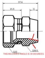
Here’s a look at how we would prepare a JIC fitting for a smooth transition attachment. Note, if the outside wall of the fitting is already tapered (for example 10° on the weld end of the female JIC) the taper on the inside need only be 10° – 20° to achieve the desired net angle of 20° – 30°.
Common End Fittings for Hose Assemblies
Beyond the pipe threads shown in the picture of nice welds above, other common end fittings include hex male NPTs, female JICs, and various kinds of fixed or floating flanges, the latter paired with stub ends.
Important Design Consideration
The outside circumference of the end fitting must overlap with the edge of the cap pass if the weld is to reach its full pressure bearing capabilities. As tube sizes are measured by outer diameter (OD) and hose sizes are measured by inner diameter (ID), the potential for a mismatch is greatest when attaching tube ends. As an example, there is little overlap between a 1” hose and a 1” tube end.
Some adjustment is needed, especially if the hose will be used in a high-pressure application. Solutions include opting for a smaller hose so there is more overlap–for instance a ¾” hose with 1” tube ends–or, if the same dimensions are needed, flaring the end of the tube to match the hose in order to create that needed overlap. This latter option would, however, also compromise pressure capacity and is not a sound practice for high pressure applications. Lastly, there are special tube size reducers, but they are expensive and also have lower pressure capacity.
Dissimilar Materials: When is it Okay?
Typically if a hose is 316L, we’ll use 316L end fittings. Using similar materials ensures the characteristics of the parent materials remain intact, and while most welders are qualified to welding procedures for joining similar materials, welding dissimilar materials requires separate weld procedures.
There is a common exception to the rule however! When working with floating flanges or raised face slip-on flanges, you’ll also need a stub end. Since the flange does not come into contact with flow media, only the stub end, the flange can be a different material and there is no issue.
Accessories
While four is the number of welds on a typical hose assembly, there are accessories added to hoses that increase this number. Accessories like an inside interlocked liner–used in high-flow applications–or an outside interlocked armor–used as an abrasion guard or bend restrictor–increase the number of welds on an assembly.
Penflex Welder Training
High caliber end fitting attachment welds are consistently achievable with proper training. Penflex offers a one-week ASME Section IX-certified program for welders with mid-level experience. The training is designed to improve technique, and perfecting fitting attachment welds is one of the skills achieved through the training.
For more information about our Welder Training Program, please click here.
Note: To print this bulletin on fitting attachment welds for metal hose assemblies, please click here.
The Art and Science of TIG Welding
Penflex’s learning and training resources make the science part easier!
Happy National Welding Month!
Have a look at the caliber of work Penflex’s welding team turns out daily.
Stop Killing Your Metal Hoses!
Avoid these 6 common hose handling mistakes for longer lasting hoses.
Preparing Hose Assemblies with NPT Ends for Leak Testing
Note: To print this bulletin on how to prepare NPT ends for leak testing, please click here.
How to Prepare NPT Ends for Leak Testing
Penflex hose assemblies undergo an air under water test followed by a hydrostatic test to ensure there are no leaks and to confirm the structural integrity of the welds.
To perform these tests, special fittings, or “closures,” are needed to create a temporary seal. It is through these fittings that the test media, whether gas or liquid, will flow.
The minimum working pressure of these fittings must meet or exceed the assembly test pressure. For instance, the test pressure in an air under water test for hose assemblies ¼” – 4” in diameter is 75 PSI. The test fittings used must have a minimum working pressure of 75 PSI.
Closures for hydrostatic testing must be stronger given the higher pressures used in these tests which, by default, is 1.5 times working pressure for an assembly with one braid layer. For instance, 4” P4 hose has a working pressure of 300 PSI. Therefore, the hydrostatic test pressure will be 450 PSI and the test fittings used must meet this pressure requirement.
Naturally any test fittings used for a hydrostatic test will work for an air under water test, but the reverse is not necessarily true.
Risk of Damage to End Fittings
Threaded pipe nipples, as well as unthreaded pipe, are susceptible to damage from wrenches during the application of the test fittings.
This is no inevitable result though! A good set-up and careful use of force will ensure no damage occurs.
Attaching the Test Fittings
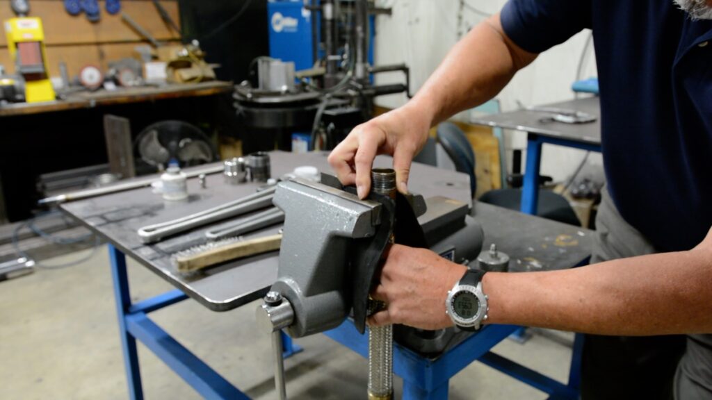
The process below is designed to minimize contact with the braided section of the hose.
- Ensure the threads are clean. Use a brush to remove any dirt or debris that could affect the ability to achieve a leak-tight seal.
- For smaller diameter hoses, a vise grip will keep the hose stable when screwing on the test fittings. Situate the hose in a piece of rubber insulation to protect the outside of the toe nipple before tightening the vise. The vise should never press against the braided hose.
- Apply a layer of thread sealing to the top half of the threads followed by Teflon pipe tape, wrapped in a clockwise direction. The combination of sealing and tape delivers a leak tight seal without requiring excessive tightening that could deform assembly fitting threads.
- Screw on the test fitting using the right size wrench, being careful not to overtighten. There is no need to bury the threads all the way into the fitting.
- Repeat on the other end of the assembly.
Pipe Thread Alternative
A hex nut is an alternative end fitting that is less susceptible to damage.
Note: To print this bulletin on how to prepare NPT ends for leak testing, please click here.
When to Request Radiographic Testing for Your Metal Hoses?
Note: To print this bulletin on radiographic testing, please click here.
You’ve fallen and banged up your arm quite badly. There are scrapes and bruises and you’re in a lot of pain. You worry something might really be wrong and so you go to the emergency room for an x-ray. The radiograph confirms what the naked eye cannot: a broken bone.
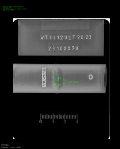
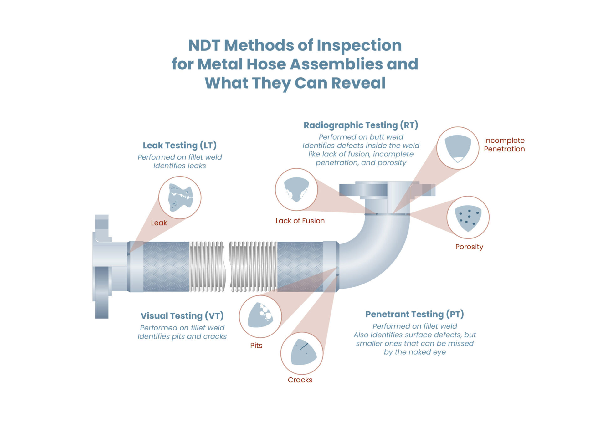
X-ray technology can be used to see the inside of a weld as well as the inside of your arm. When electromagnetic waves pass through a material, the image rendered will reveal any imperfections. For instance, the digital reading below from an RT inspection on a butt weld shows slight darkness within the weld. This is an indication of incomplete fusion.
Welds that pass RT inspection will show complete fusion and be absent of any porosity.
The Most Sensitive NDT Methods
Any discussion of non-destructive testing (NDT) for metal hoses would be remiss if it failed to acknowledge the limited scope of methods used.
There are numerous NDT methods, some of which contain multiple techniques for reaching similar conclusions though with varying levels of granularity given the use of different equipment and the adherence to different processes.
Leak testing (LT) is the most common NDT method for metal hoses. All Penflex hoses undergo LT inspection of seam and orbital welds. If being made into assemblies, the hoses are then subjected to air under water and hydrostatic tests to assess end fitting connections. For certain applications, we can use a helium mass spectrometer to identify even smaller leaks. While these techniques allow us to identify current leaks, they offer no indication of whether future leaks may occur.
For this, we may perform penetrant inspection (PT) on the hose. PT highlights surface defects like pits or cracks that could develop into leaks once the hose is in operation.
And, while Radiographic Testing (RT) is most often used on full penetration butt welds on pipe, tank and plate joints, if requested, we can support Radiographic Testing (RT) of hoses–whether that be to inspect the longitudinal seam or the end fitting connection welds. RT is included within a subset of NDT inspection called volumetric testing, which entails looking at the whole mass from top to bottom. These are the most sensitive NDT methods.
Governed by ASME
RT is typically a request in scenarios where failure presents serious risks to safety. These could be applications in aerospace or nuclear power plants, for example. Radiographic testing gives piping system owners and equipment manufacturers greater assurance that components will perform as expected in the intended application. In other applications, such assurances may be unnecessary.
While RT does provide an additional means of measuring quality, it is also a requirement for compliance with ASME B31.3, the organization’s standard for process piping systems. If a plant is ASME B31.3 compliant, its pipe and hoses must be compliant with the code as well. Radiographic testing is among the requirements for compliance.
All NDT examination methods are outlined in Section V of the ASME Boiler and Pressure Vessel Code. Radiographic testing requirements, methods and techniques are detailed in Article 2 of the 1000-page-plus document.
RT in Combination with Other NDT Methods
ASME B31.3 often requires RT inspection in combination with another NDT method, typically visual inspection (VT). If a component fails VT, it would not then be subjected to RT. Beyond avoiding unnecessary testing, combining methods provides a more comprehensive view of the finished assembly in all aspects of surface conditions and weld quality.
The requirements for testing depend on fluid service. For instance, Category D Fluid Service covers non-flammable and non-toxic media flowing through the hose at temperatures ranging from -20°F to – 366°F at a maximum pressure of 150 PSI. Hoses used in this fluid service must undergo air under water and hydrostatic tests, as well as VT inspection, and 5% of each welder’s work is subjected to radiographic testing.
Then consider the requirements for Category M Fluid Service which governs highly toxic media flow. Air under water and hydrostatic tests are followed by VT and finally RT on 20% of all butt and miter joints.
Challenges of Radiographic Testing
The most obvious challenges to RT inspection include the equipment requirements, administration of inspection by qualified personnel, and the necessity of carrying out testing far from personnel or in a protected space where radiation can be contained.
The inspector needs a good set-up to take the right views and must be well versed in what they are looking at. While the code focuses on RT inspection of butt welds, radiographic testing can be carried out on any type of weld. This may present a challenge for metal hosers as some labs may never have seen the cap weld to fillet weld connections that are so ubiquitous in our industry.
For a successful inspection, the tester must understand the “load path” from end fitting to hose into braid.
Radiographic Testing Requirements for a Weld Shop
Beyond satisfying user requirements, RT inspection is used to demonstrate a welder’s capability. As a shop that does work per ASME B31.3, Penflex must test at least 5% of all butt welds performed by each welder on a routine basis whether the work itself has a B31.3 requirement or not.
A welder who consistently passes RT inspection is a very skilled welder indeed.
This butt weld connecting a 304 stub end to a concentric reducer is an example of a high quality weld. Something like this would be used as part of the 5% requirement.
Note: To print this bulletin on radiographic testing, please click here.
What Does ASME B31.3 and B31.1 Compliance Mean for Metal Hoses?
Note: To print this bulletin on ASME B31.3 and B31.1 compliance, please click here.
ASME Compliance for Metal Hoses
The terms ASME B31.3 and B31.1 get tossed around a lot in our industry, but what does compliance with these oft-cited standards really mean?
ASME Standards for Piping Systems
The American Society of Mechanical Engineers (ASME) has established numerous standards for the design, manufacture and testing of various “mechanical devices” over its long history. Its aim has been and remains today to ensure safety and reliability.
Among these mechanical devices are piping systems, and one of the first standards issued by the organization was, in fact, related to pipe. “Standard for the Diameter and Overall Dimensions of Pipe and Its Threaded Ends” was issued in 1887 and sought to address issues around pipe standardization emerging with the advent of mass manufacturing.
Since then, all piping standards issued by ASME come under the umbrella of the B31 Series. B31.3 and B31.1 are standards within the B31 Series. There are others.
ASME B31.3 for Process Piping
ASME B31.3 contains the requirements for piping systems found in the industries where metal hose is most often used: petroleum refining, chemical manufacturing, pulp and paper, semiconductors, cryogenics, etc.
It covers everything related to the piping system including those critical flexible components–metal hoses. The sections related to metal hose discuss material composition, design parameters, welding procedures and minimum testing requirements.
Some rules cite compliance with another ASME standard. For instance, standards for flanges are laid out in ASME B16.5. If a hose assembly with flanges is to comply with B31.3, its flanges need to comply with B16.5.
Similarly, other rules cite compliance with standards administered by different organizations. For instance, metal hoses must be specified to BS 6501, Part 1, a standard from the British Standards Institute that compliments ISO 10380, a standard from the International Organization for Standardization.
Categories of Fluid Service
Not all hoses are treated equally within ASME B31.3. The code divides pipes and hoses into six service categories based on flow media and operating conditions.
- Category D Fluid Service
- Category M Fluid Service
- Normal Fluid Service
- High-Pressure Fluid Service
- Elevated Temperature Fluid Service
- High Purity Fluid Service
The parameters for categorization determine testing and design requirements. For instance, pressure ratings of 2500 psi or greater would require compliance with High Pressure Fluid Service, and based on the testing requirements are going to be more applicable to hard pipe than to thinner-wall hose.
Those requirements are found in Chapter IX of ASME B31.3 and include the following:
- Charpy impact testing
- Liquid penetrant examination (LT)
- 100% Radiography inspection (RT)
- Hydrostatic or pneumatic/gas testing at 1.25 times working pressure
These requirements are more stringent than the requirements for hoses used in Category D Fluid Service, where media is non-flammable, non-toxic, and will not exceed 150 psi at service temperatures between -20°F and 366°F.
- Visual examination
- 5% RT inspection
- Air under water test at 1.5 times working pressure
A hose may be ASME B31.3 compliant if it meets the requirements for Category D Fluid Service, but that same hose will not necessarily also be compliant with ASME B31.3, Chapter IX for High Pressure Fluid Service.
If a hose will not be used in service as defined by Category D, Category M, High-Pressure, Elevated Temperature, or High Purity, it would be considered for use in Normal Fluid Service.
While this is the most common use case for metal hoses, it’s worth pointing out just how comprehensive the code is (fluid service categories are just one example) to highlight that compliance with the code usually means compliance with certain sections or appendices rather than with the entire code.
ASME B31.1 for Power Piping
ASME B31.1 contains the requirements for piping systems in electric power generating stations, industrial and institutional plants, geothermal heating systems, and central and district heating and cooling systems. The flow media is most often water or steam.
With a more defined application, ASME B31.1 does not have the same need for separate service categories. The codes are similar to a certain degree though, broadly speaking, because the impact of a shutdown at a power plant can affect many thousands of people immediately, the requirements are more stringent to ensure a greater level of reliability. As an example, while ASME B31.3 references BS 6501 for the metal hose requirements, B31.1 has specific sections concerning them.
On the other hand, some requirements for hoses are the same. Both standards reference Section IX of ASME’s Boiler and Pressure Vessel Code (BPVC).
ASME Section IX
“Section IX: Welding, Brazing and Fusing Qualifications” of ASME’s BPVC sets the standard for quality welding. Welds must be performed in accordance with a documented Weld Procedure Specification (WPS) by a welder certified to code.
ASME Section IX is similarly comprehensive and not all sections relate to welding metal hose. Due to the quality materials in play, TIG welding is the preferred end fitting attachment method. Only the parts of Section IX relating to gas tungsten arc welding (GTAW), another term for TIG, are relevant.
How Relevant are ASME Codes in the Metal Hose Industry?
These codes are voluntary. Their use ranges across industries and across companies within those industries. Many users don’t require ASME compliant hoses. Many do. Even if there is no requirement for ASME compliance, many components, like flanges, will comply with B16.5 automatically.
There is also overlap between sound design and manufacturing processes and the ASME codes. For instance, Penflex is capable of fabricating hose assemblies to conform to either B31.3 or B31.1, but we would not do so unless compliance is required per the customer.
That said, there are many aspects of our production that inherently align with the code, like our standard air under water leak test. The fact that all Penflex welders are ASME Section IX certified would be another example. End fitting attachment welds are going to be done by ASME Section IX qualified welders, even if there is no requirement for this by the end user.
If compliance is requested, a certification is typically issued by the quality department to confirm design, testing and welding was carried out in accordance with the respective section or sections of the pertinent code.
Along with material selection, code compliance is another decision dictated by the piping system owner. Their ability to communicate clearly the relevant sections of these, or any other, codes helps to identify suppliers capable of meeting their needs.
Note: To print this bulletin on ASME B31.3 and B31.1 compliance, please click here.